Void Generation#
GEOUNED includes two innovative automatic void generation capabilities: enclosures and envelopes. These capabilities are detailed below.
User-defined enclosures
Enclosures are CAD-defined solids used as the base for generating the void of the region they cover, instead of the usual bounding box that covers the region of interest. The use of user-defined enclosures makes it possible to generate separate void regions within the same model. This is useful for assigning different materials to the void (e.g., different air compositions between rooms) and for later user modifications of the geometry. In addition, enclosures can be nested, making it easy to give the void a hierarchical structure. In summary, user-defined enclosures are a very useful capability for generating clean and structured voids.
Enclosures are defined directly in the CAD model with the component name enclosureX_Y_, where X is the ID number of the enclosure and Y is the enclosure that enclosure X depends on (at the lowest level, Y is 0).
For example, enclosure1_0_ is enclosure 1, which has no enclosure above it, and enclosure2_1_ is enclosure 2, which is nested under enclosure 1.
There is no restriction on the level of nesting between enclosures.
Also, each enclosure must be completely inscribed within its parent enclosure (part of an enclosure cannot lie outside its parent enclosure).
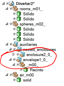
Enclosure solids can be defined anywhere in the CAD model tree. By default, the void cells corresponding to each enclosure are written in the MCNP output file after all the solid definitions, regardless of their position in the CAD model tree. Enclosures appear in the output file in the same order (top to bottom) as in the CAD model tree. The last void cells written to the output file are the level-0 voids, i.e., those outside any enclosure.
If the sortEnclosure option parameter is set to True, the enclosure voids are written in the output file interleaved with the solid cell definitions. They are written in the same order in which they appear in the CAD model tree, regardless of whether solid cells are defined before or after the enclosure solid.
Envelopes
In some cases, excluding a region from void generation can be useful for producing more optimized MCNP models. For example, if a region of space is full of other components, an envelope solid covering this region (usually simpler than the components it covers) can be defined in the CAD model. During void generation, this envelope is used to ignore all the components inside it (only components completely inside the envelope are excluded from the void generation process). This should produce a simpler void definition. In return, the user must ensure that the region covered by the envelope is clean (i.e., free of lost particles) and completely filled. Envelopes follow the same naming convention as enclosures, using the text ‘envelope’ instead of ‘enclosure’. Dependency has no meaning in this case, since only the highest level is used in the void generation process.